Creating floor finishes is a task that can be automated easily and save us a huge amount of time. When room finishes are defined or embedded in a room’s parameter, it is nonsense to start modeling the floor finishes manually.
So forget about modeling every floor for every floor finish that is in the project manually. The following script will deal with the rooms that have only a single line as boundary and will give you ideas on how to deal with the more complex ones.
Floor finish from rooms in Dynamo

Group 01 – INPUT group is where the final user can choose the level to place the floor finishes, obviously it matches the level where the rooms are located. Also, it allows the user to set the offset from that level.

Group 02 – The first subgroup selects all the rooms in the project. The next one filters out all the rooms that are not placed in the model. The third one selects the rooms with the Floor Finish parameter filled and the last one filters the rooms that are in the selected Level.

Group 03 – This group retrieves all the faces from the rooms as surfaces, collects the center of all those surfaces and checks for the Z coordinate. After, it sorts and selects the faces that have coordinate Z = 0. Finally, it collects the curves from the surfaces to use them as floor boundaries.

The reason why some nodes have Preview deactivate is that they create preview elements, in this case, surfaces that recreates the volume of the room, in Revit that block the floors created by the script.
Group 04 – It collects the content of the Floor Finish parameter of the rooms and retrieves the same floor types from the model.
Important point: The Floor Finish parameter must match a floor type name in the model, otherwise the floor will not be created and the script might break.

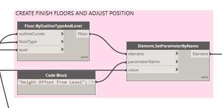
Group 05 – Creates the floors in the model and sets the desired offset if selected by the user.
Group 06 – This last one group all the newly created floors. The benefit of grouping them is that you can run the script next time and it will modify all of them without you have to worry about the previous floors. Say you move a wall, the floor won´t match the new boundaries and you would have to delete the previous one before creating the new one. Grouping them avoids issues as Revit will overwrite the content of the old group with the new one.

Here you can download the script:
DEVELOPMENT IDEA:
There are multiple possibilities to expand this script. One of them is to increase the ability of our script to slipt the boundaries of rooms with islands into two closed poly curves. In this way, the script would overcome the issue of the Revit API not allowing the creation of floors with holes inside.
Leave a Reply